SAML for Motion Based Lighting System
Project Description
This project implements an automated motion detection and response system using a sensor-controller-actuator architecture. A motion sensor continuously monitors for movement within its detection range. Upon detecting motion, the sensor transmits a signal to a controller (or router) responsible for processing the incoming data. The controller analyzes the signal and, based on predefined logic, sends a command to a light actuator to turn the light on. This system enables responsive, energy-efficient lighting by automating illumination based on occupancy or movement detection, making it ideal for smart home or smart building applications.
Motion Sensor
- Detects Motion every second
- Sends the data to the controller/router
Controller/Router
- Waits for the message to receive
- Look for the available nodes/lights
- Sends the message
Sensor/Light
- Receives the message.
- checks if it's 1 or 0.
- Turn on/off the light based on the condition.
Steps to Create a SAML Project
1. Create a New SAML Project
- Open Eclipse and go to
File→New→Project. - Select
EMF→Empty EMF Project. - Name the project and select a location (keeping the default workspace location is recommended).
- Click
Finish.
2. Create the SAML Model File
- In the Project Explorer, expand the newly created project.
- Right-click on the
modelfolder, selectNew→Other. - Search for
CAPSModeland selectCAPSSaml. - Name the file, ensuring it ends with
.capssaml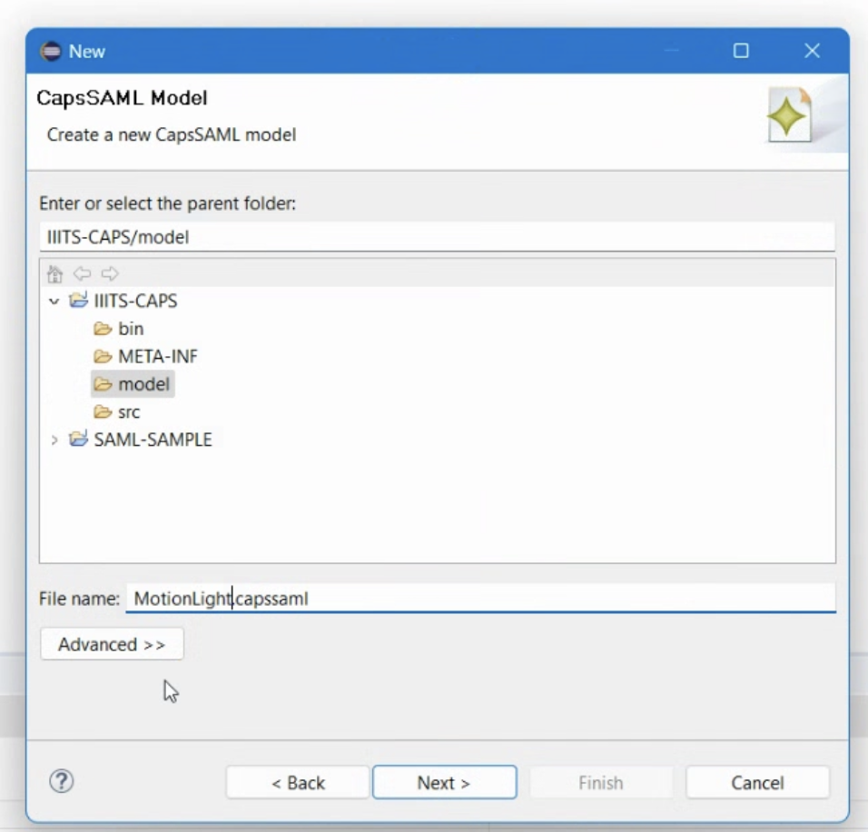
- Click
Next, selectSoftware Architecturefrom the model object list, and clickFinish.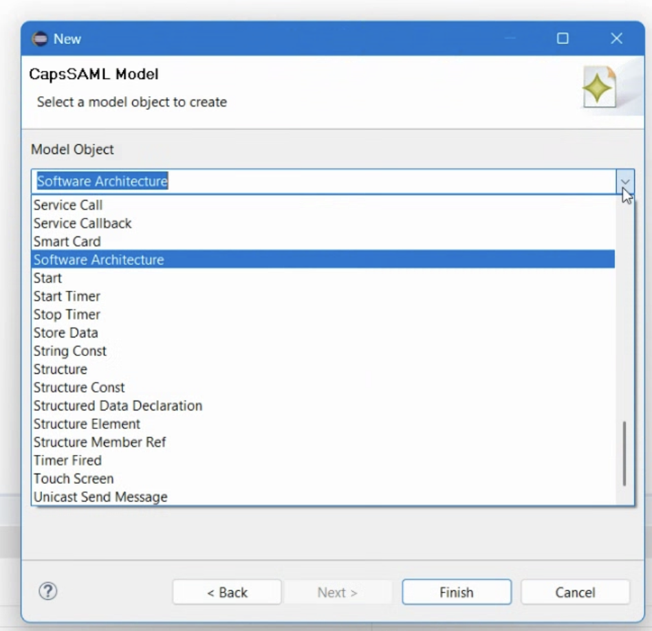


3. Initialize the Diagram
- In the Project Explorer, right-click on the new
.capssamlfile. - Select
Initialize friends diagram file.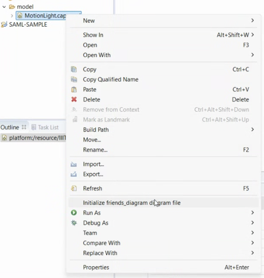
- Keep the default name and location, and click
Finish. - The diagram editor will open with an empty canvas.

4. Creating Components
1. Motion Sensor:
- From the palette, select
Componentand place it on the canvas.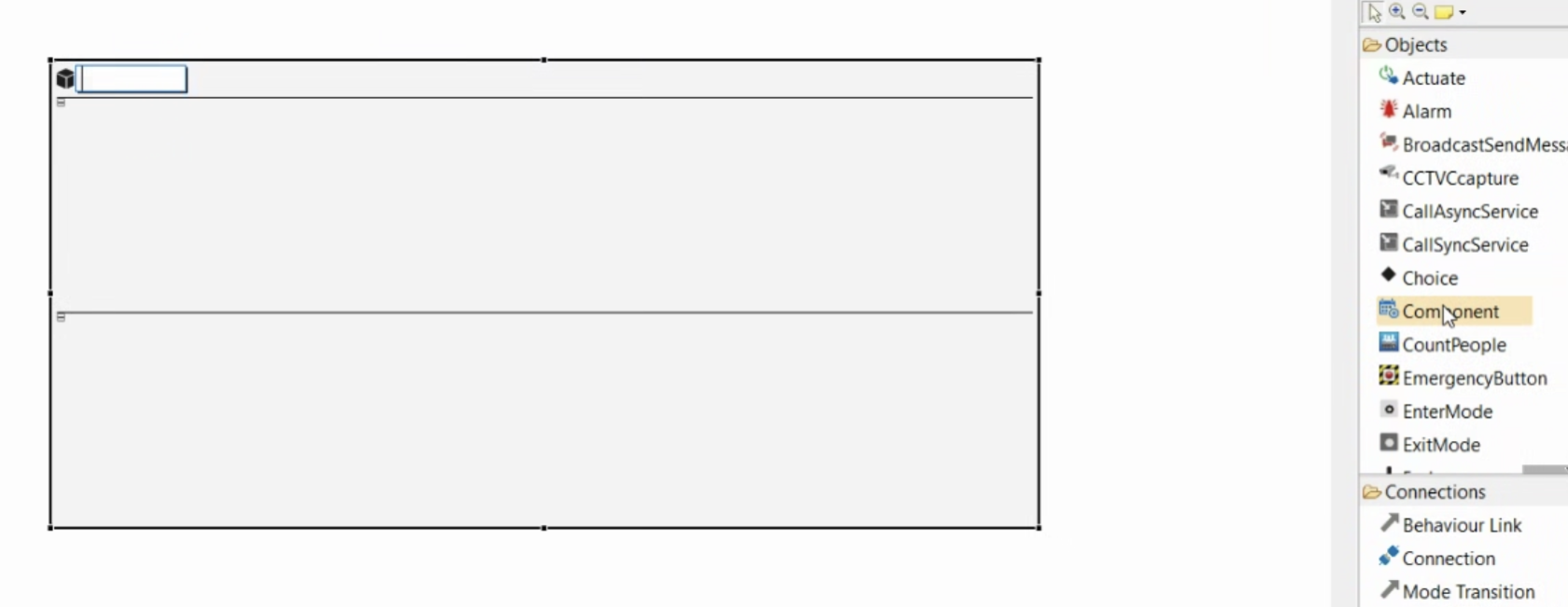
- In the Properties view, name it
MotionSensor.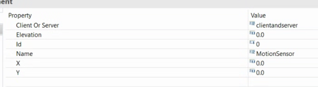
- Inside the component, add:
Initial Mode(to define its starting behavior).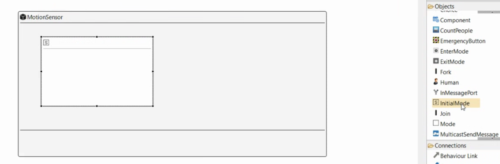
StartTimer(to trigger periodic temperature readings).SenseOccupancy(to simulate temperature sensing).TimerFired(to handle the timer expiration event).UnicastSendMessage(to send the motion data).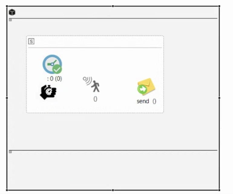
- Connect these elements using
Behavior Link.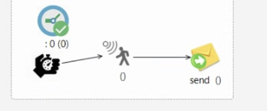
- Set StartTimer Properties:
Cyclic→TrueName→MotionTimerPeriod→1000(milliseconds, i.e., every 1 second)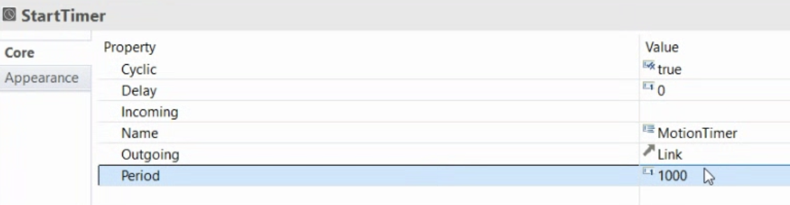
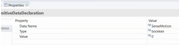
- Define
Primitive Data Declaration:Name→MotionDataType→BooleanValue→0
- ``
-
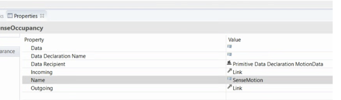
Select the
SenseOccupancyitem and, in the properties view, set the following parameters.- Data Recipient →Double click and select the Motion Data
-
Name →SenseMotion
 - Select the message item and set the following parameters:
- Data →MotionData;
- Data Recipient →Select the Primitive Data Declaration MotionData variable;
- Name →MotionValue
- Select the message item and set the following parameters:
- Data →MotionData;
- Data Recipient →Select the Primitive Data Declaration MotionData variable;
- Name →MotionValue 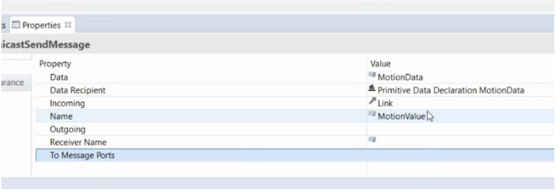


Now add one OutMessagePort and connect the send MotionValue to the outport using the Send Message Port. You will see something similar to this at this moment:

2. Controller/Router
- Create a
ComponentnamedController. - Inside, add:
Initial ModeReceiveMessage(to get motion data from the sensor)Choice(to implement decision-making logic)- Two
UnicastSendMessageinstances (to sendOnorOffcommands)
- Define
Primitive Data Declaration:Name→Off,Type→Boolean,Value→FalseName→On,Type→Boolean,Value→True
- Select the message item and set the following parameters for one:
- Data →Off;
- Data Recipient →Select the Primitive Data Declaration Off
- Name →SendOff
- Select the message item and set the following parameters for second:
- Data →On;
- Data Recipient →Select the Primitive Data Declaration On
- Name →SendOn
- Connect elements with
Behavior Link:ReceiveMessage→ChoiceChoice→SendOnMessage(if motion==1)Choice→SendOffMessage(if motion==0)
- Add the InMessagePort, connect to the Receive MotionValue using the ReceiveMessage Port, and 2 OutMessagePorts, and connect them to the UniCastSendMessage

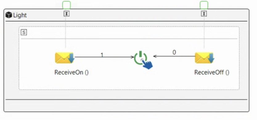
3.Sensor/Light
- Create a
ComponentnamedLight. -
- Inside, add:
-
Initial Mode- TwoReceiveMessageinstances (one forOn, one forOff) -Actuate(to control the window mechanism) - Connect elements with
Behavior Link:ReceiveOpenMessage→Actuate(if 1 = True)ReceiveCloseMessage→Actuate(if 0 = False)
- Inside, add:
-
- Now add two InMessagePorts and connect them to the two ReciveMessage using the ReceiveMessagePort

4. Final Connections
- Use
OutMessagePortandInMessagePortto link using the Connection- MotionSensor -> Router
- Router(SendOn) to Light(ReceiveOn)
- Router(SendOff) to Light(ReceiveOff)
Final Diagram:

Save it and now, open the File in VSCode or in any code editor to see the XML file generated.